Overview and source of
overvoltage
•
When
the voltage in a circuit or part of it is raised above its upper design limit,
this is known as over voltage.
•
The
conditions may be hazardous. Depending on its duration, the over voltage event
can be permanent or transient, the latter case also being known as a voltage
spike.
•
Electronic
and electrical devices are designed to operate at a certain maximum supply
voltage, and Considerable damage can be caused by voltage that is higher than
that for which the devices are rated.
•
For
example an electric light bulb has a wire in it that at the given rated voltage
will carry a current just large enough for the wire to get very hot (giving off
light and heat), but not hot enough for it to melt.
•
The
amount of current in a circuit depends on the voltage supplied: if the voltage
is too high, then the wire may melt and the light bulb has "burned
out".
•
Similarly
other electrical devices may stop working, or even maybe burst into flames if
an over voltage is supplied to the circuit of which these devices are part.
•
Natural
-A typical natural
source of transient over voltage events is lightning.
•
Man-made- sources are spikes usually caused by
electromagnetic induction when switching on or off inductive loads (such as
electric motors or electromagnets)
•
One
of the purposes of electromagnetic compatibility compliance is to eliminate
such sources.
•
Conduction
path- The transient
pulses can get into the equipment either by power or data lines, or over the
air from a strong electromagnetic field change - an electromagnetic pulse
(EMP).
•
Filters
are used to prevent spikes entering or leaving the equipment through wires, and
the electromagnetically coupled ones are attenuated by shielding.
Power systems are always subjected to over voltages that have their origin in :
Atmospheric discharges
in which case they are called external or lightning over voltages, or - The
latter type are called internal over voltages - This classes may be further
subdivided into
(i)
Temporary
over voltages, if they are oscillatory of power frequency or harmonics
Temporary over voltages occur almost without
exception under no load or very light load conditions.
whereas that of internal
or switching overvoltages increases with increasing the operating voltage of
the system.
(ii) Switching over
voltages, if they are heavily damped and of short duration they are generated
internally by connecting or disconnecting the system, or due to the systems
fault initiation or extinction.
•
The
magnitude of the external or lightning over voltages remains essentially
independent of the system’s design, Hence, with increasing the system’s
operating voltage a point is reached when the switching over voltages become
the dominant factor in designing the system’s insulation
•
Because
of their common origin the temporary and switching over voltages occur together
and their combined effect has to be taken into account in the design of h.v.
systems insulation.
•
Up
to approximately 300 kV, the system’s insulation has to be designed to
withstand primarily lightning surges.
•
Above
that voltage, both lightning and switching surges have to be considered.
•
For
ultra. systems, 765 kV and above switching over voltages in combination with insulator
contamination become the predominating factor in the insulation design.
Switching Surges
Over voltage Due to Switching Surges, System Faults and Other Abnormal Condition
•
Unlike
the lightning voltages, the switching and other type of overvoltages depend on
the normal voltage of the system and hence increase with increased system
voltage.
•
In
insulation coordination, where the protective level of any particular kind of
surge diverter is proportional to the maximum voltage, the insulation level and
the cost of the equipment depends on the magnitudes of these overvoltages.
•
In
the EHV range, it is the switching surge and other types of overvoltages that
determine the insulation level of the lines and other equipment and
consequently, they also determine their and costs.
Origin of Switching Surge
•
The
making and breaking of electric circuits with switch gear may results in
abnormal overvoltage in power systems having large inductance and capacitances.
•
The
overvoltages may go as high as 6 times the normal power frequency voltage.
•
In circuit breaking operation, switching
surges with a high rate of rise of voltage may cause repeated restricting of
the arc between the contacts of a circuit breaker, thereby causing destruction
of the circuit breaker contacts.
Control of Over voltages Due to Switching
•
Insertion
of Resistors
•
Phase
Controlled Switching
•
Drainage
of Trapped Charge
•
Shunt
Reactor
Lightening
•
Physical
manifestations of lightning have been noted in ancient times, but the understanding
of lightning is relatively recent.
•
The
real incentive to study lightning came when electric transmission lines had to
be protected against lightning.

The methods include
measurements of:
(i) lightning currents,
(ii) magnetic and
electromagnetic radiated fields,
(iii) voltages,
(iv) use of high-speed
photography and radar.
•
Fundamentally,
lightning is a manifestation of a very large electric discharge and spark.
•
In
an active thunder cloud the larger particles usually possess negative charge
and the smaller carriers are positive.
•
Thus
the base of a thunder cloud generally carries a negative charge and the upper
part is positive, with the whole being electrically neutral.
•
There
may be several charge centers within a single cloud. Typically the negative
charge centre may be located anywhere between 500m and 10 000m above ground.
•
Lightning discharge to earth is usually
initiated at the fringe of a negative charge centre together with the current
to ground.
•
The
stroke is initiated in the region of the negative charge centre where the local
field intensity approaches ionization field intensity (セD30 kV/cm in
atmospheric air, or セ10
kV/cm in the presence of water droplets).
•
To
the eye a lightning discharge appears as a single luminous discharge - although
at times branches of variable intensity may be observed which terminate in
mid-air - while the luminous main channel continues in a zig-zag path to earth.
•
High-speed photographic technique studies
reveal that most lightning strokes are followed by repeat or multiple strokes
which travel along the path established by the first stroke.
•
The
latter ones are not usually branched and their path is brightly illuminated.
•
The
current in the return stroke is in the
order of a few kA to 250 kA and the temperatures within the channel are 15 000ーC to20 000ーC and are
responsible for the destructive effects of lightning giving high luminosity and
causing explosive air expansion.
•
The return stroke causes the destructive
effects generally associated with lightning
•
The
return stroke is followed by several strokes at 10- to 300-m/sec intervals. The
leader of the second and subsequent strokes is known as the ‘dart leader’
because of its dart-like appearance.
•
The
dart leader follows the path of the first stepped leader with a velocity about
10 times faster than the stepped leader. The path is usually not branched and
is brightly illuminated.
Representation of various stages of lightning stroke between cloud and ground

Distribution of times
to crest of lightning stroke currents

Energy in
lightning
•
To
estimate the amount of energy in a typical lightning discharge let us assume a
value of potential difference of 107 V for a breakdown between a cloud and
ground and a total charge of 20 coulombs.
•
Then
the energy released about 55 kWh in one
or more strokes that make the discharge.
•
The
energy of the discharge dissipated in the air channel is expended in several
processes.
•
Small
amounts of this energy are used in ionization of molecules, excitations,
radiation, etc. Most of the energy is consumed in the sudden expansion of the
air channel.
•
Some
fraction of the total causes heating the struck earthed objects. In general, lightning
processes return to the global system the energy that was used originally to
create the charged cloud.

Nature of danger
•
The
degree of hazard depends on circumstances.
•
To minimize the chances of being struck by
lightning during thunderstorm, one should be sufficiently far away from tall
objects likely to be struck, remain inside buildings or be well insulated.
•
A
direct hit on a human or animal is rare;
•
they
are more at risk from indirect striking, usually:
•
(a)
when the subject is close to a parallel hit or other tall object,
•
(b)
due to an intense electric field from a stroke can induce sufficient current to
cause death, and
•
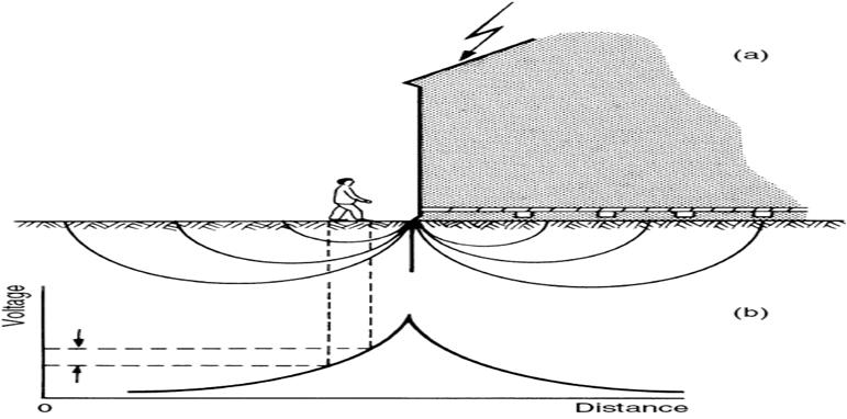
(c)
when lightning terminating on earth sets up high potential gradients over the
ground surface in an outwards direction from the point or object struck.
•
The
potential difference between the person’s feet will be largest if his feet are
separated along a radial line from the source of voltage and
•
will
be negligible if he moves at a right angle to such a radial line.
•
In
the latter case the person would be safe due to element of chance.qualitatively
the current distribution in the ground and the voltage distribution along the
ground extending outwards from the edge of a building struck by lightning.
Traveling Wave on
Transmission Line
- Any disturbance on a transmission
line or system such as a sudden opening or closing of line, a short
circuit or a fault results in the development of overvoltage or
overcurrent at that point.
- This
disturbance propagates as a traveling wave to the ends of the line or to a
termination, such as, a sub-station.
- Usually
these traveling waves are high frequency disturbances and travel as waves.
They may be reflected, transmitted, attenuated or distorted during
propagation until the energy is absorbed.
- Long
transmission lines are to be considered as electrical networks with
distributed electrical elements.
Attenuation and
Distortion of Traveling Waves
•
As
a traveling wave moves along a line, it suffers both attenuation and distortion.
The decrease in the magnitude of the wave as it propagates along the line is called
attenuation
•
The
elongation or change of wave shape that occurs is called distortion. Sometimes,
the steepness of the wave is reduced by distortion. Also, the current and
voltage wave shape become dissimilar even though they maybe the same initially.
•
Attenuation
is caused due to the energy loss in the line and distortion is caused due to
the inductance and capacitance of the line.
Reflection and
Transmission of Waves at Transition Points
•
Whenever
there is an abrupt change in parameters of a transmission line, such as an open
circuit or a termination, the traveling wave undergoes a transition, part of
the wave is reflected or sent back and only a portion is transmitted forward.
•
At
the transition point, the voltage or current wave may attain a value which can
vary from zero to two times its initial value.
•
The
incoming wave is called the incident wave and the other wave are called the reflected
and transmitted waves at the transition point.