1. Differential Protection
Differential protection is generally unit protection. The protected zone is exactly determined by location of CT's and VT's. The vector difference is achieved by suitable connections of current transformer or voltage transformer secondary.
"A differential relay responds to vector difference between two or more similar electrical quantities "
1- The differential relay has at least two actuating quantities say I1, I2
2- The two or more quantities should be similar i.e. current/current.
3- The relay responds to the vector difference between the tow i.e. to I1-I2, which includes magnitude and/or phase angle difference.
2. Application of differential protection :-
Most differential relays are current differential relays in which vector difference between the current entering the winding and current leaving the winding is used for sensing and relay operation.
Differential protection principle is used in the following applications.
- Protection of generator, protection of generator transformer unit.
- Protection of transformer
- Protection of feeder (transmission line) by pilot wire differential protection.
- Protection of transmission line by phase comparison carrier current protection.
- Protection of large motor.
- Bus-zone protection.
3. Principle of circulating current differential (MERZ-PRIZE) protection
Fig. (1-a) illustrates the principle of differential protection of generator and transformer, X is the winding of the protected machine. Where there is no internal fault, the current entering in X is equal in phase and magnitude to current leaving X. The CT's are of such a ratio that during the normal conditions or for external faults (Through Faults) the secondary current of CT's are equal. These current say I1 and I2 circulate in the pilot wire. The polarity connections are such the current I1 and I2 are in the same direction of pilot wire during normal condition or external faults. Relay operation coil is connected at the middle of pilot wires. Relay unit is of over current type.

During normal condition and external fault the protection system is balanced and the CT's ratios are such that secondary currents are equal. These current circulate in pilot wires. The vector differential current I1- I2 which flow through the relay coil is zero.
I1-I2 = 0 (normal condition or external faults)
This balance is disturbed for internal faults. When fault occurs in the protected zone, the current entering the protected winding is no more equal to the leaving the winding because some current flows to the fault. The differential I1-I2 flows through the relay operation coil and the relay operates if the operating torque is more than the restraining torque.
The current I1 and I2 circulate in the secondary circuit. Hence CT's does not get damaged.
Polarities of CT's are considered. CT's are connected such that the circulating currents I1and I2 are as shown in Fig. (1-a) for normal condition.
4. Difficulties of differential protection : -
4.1 Difference in pilot wire lengths.
The current transformer and machine to be protected are located at different sites and normally it is not possible to connect the relay coil to the equipotential points. The difficulty is overcome by connecting adjustable resistor in series with the pilot wires. These are adjusted on site to obtain the equipotential points
4.2 CT's ratio error during short circuits.
The current transformer may have almost equal ratio at normal currents. But during short circuit conditions, the primary currents are unduly large. The ratio error of CT's on either side differ during these condition due to :
i) Inherent difference in CT characteristic arising out of difference in magnetic circuit, saturation conditions etc.
ii) Unequal d.c. component in the short circuit current.
4.3 Saturation of CT magnetic circuit during short circuit condition.
Due to these causes the relay may operate even for external faults. The relay may loose its stability for through faults.
To overcome these difficulty, the percentage differential relay, or 'Based Differential Relay' is used. It is essentially a circulating current differential relay which additional restraining coil. The current flowing in restraining coil proportional to (I1+I2)/2 and this restraining current prevents the operation during external faults. Because, with the rise in current, the restraining torque increases and I1-I2 arising out of difference in CT ratio is not enough to cause the relay operation.
4.4 Magnetizing current inrush in transformer while switching in.
When the transformer is connected to supply, a large (6 to 10 times full load) current inrush takes place. This certainly causes operation of differential relay current inrush takes place. This certainly causes operation of differential relay though is no fault in the transformer. To avoid this difficulty harmonic restraint is provided for the differential relay. This relay filter the harmonic component from the inrush current and feeds it to the restraining coil. The coil magnetizing current contains a large content of several harmonics. This harmonic content is used for obtaining restraining torque during switching in of transformer.
4.5 Tap changing. The tap changing causes change in transformation ratio of a transformer.
Thereby the CT ratio do not match with the new tap settings, resulting in current in pilot wires even during health condition. This aspect is taken care of by biased differential relay.
5. Differential protection of 3-phase circuit :
Referring to Fig. (2) during the normal conditions the three secondary currents of CT's are balanced and current flows through the relay coil. During fault in the protected zone, the balance is distributed and differential current flows through the relay operating coil. The differential current is above the pick up value, the relay operates.
Secondary of CT is never left on open circuit

6. Biased or per cent differential relay
The reason for using this modification is circulating current current differential relay is to overcome the trouble arising out of differences in CT ratios for high values of external short circuit currents.
(Refer the previous paragraph). The percentage differential relay has an additional restraining coil connected in the pilot wire as shown in Fig. (3).
In this relay the operating coil is connected to the mid-point of the restraining coil becomes the sum of ampere turns in its tow halves, i.e (I1N/2) + (I2N/2) which gives the average restraining current of (I1 + I2)/2 in N turns. For external faults both I1 and I2 increase and thereby the restraining torque increases which prevents the mal-operation.
The operating characteristic of such a relay is given in Fig. (4).
The ratio of differential operating current to average restraining current is Fixed percentage.
Hence the relay is called 'percentage differential relay'.
The relay is so called 'Based differential relay' because the restraining coil is also called a biased coil as it provides additional flux.


The percentage of biased differential relay has a rising single pick up characteristic. As the magnitude of through current increases, the restraining current decreases.
7. Setting of differential relay :
The circulating current differential relay has tow principle settings namely,
- Setting of operating coil circuit.
- Setting of restraining coil circuit.
Setting of operating coil circuit (Basing setting). The percentage setting of (Basic setting) of operating coil circuit is defined as the ratio :

(when the current in restraining coil is zero)
Setting of restraining coil circuit (pick up value). It is defined as the ratio :

While determining this setting the factors be considered include
- Ct errors -Tap-changing
- Resistance of pilot wires - Stability of through faults
In case of power transformers, percentage basic setting is of the order of 20 % and percentage pick-up value of the order of 25%.
8. Balanced voltage differential protection
Fig. (5) illustrates the principle of differential protection based on balanced voltage principle.
In this the secondaries of CT's are connected such that for normal conditions and through fault conditions, the secondary current of CT's on tow sides opposes each other and their voltage are balanced Fig. (5-a). During internal fault, the condition changes as illustrated in Fig. (5-b) an equivalent current (I1 +I2)/2 flows through relay coils at each end.
The current transformer used in such protection are with air gap core so that the core does not get saturated and overvoltages are not produced during zero secondary current under working normal condition.

Differential Protection of Feeders (Pilote Wire Protection)
Feeder and busbar protection
In differential protection scheme, the current entering at one end of the line and leaving from other end of the line is compared. The pilot wires are used to connect the relays. Under normal working condition, the two currents at both ends are equal and pilot wires do not carry any current, keeping relays inoperative. Under fault conditions, The two currents at two ends are no longer same, this causes circulating current flow through pilot wires. This causes relays to trip which operate the circuit breakers to isolate the faulty section.
The various schemes used with this method of protection are,
1. Merz-Price voltage balance system
2. Translay scheme
Merz-Price Voltage Balance System
The Fig. 1 shows Merz-Price voltage balance system used for the three phase feeders.

Under normal condition, current entering the line at one end is equal to current leaving from the other end.
Thus equal and opposite voltages are induced in the secondaries of C.T.s. at the two ends. Hence no current flows through relays.
Under fault condition, two currents at the two ends are different. Thus the secondary voltages of the two C.T.s also differ. This circulates a circulating current through the pilot wires and the relays. Thus the relays trip the circuit breakers to isolate the faulty section.
The advantages of this method are,
1. Can be used for parallel as well as ring main system.
2. Provides instantaneous protection to the ground faults.
The limitations of this method are,
1. The C.T.s used must match accurately.
2. The pilot wires must be healthy without discontinuity.
3. Economically not suitable as the cost is high due to long pilot wires.
4. Due to long pilot wires, capacitive effects may affect the operation of the relays.
Translay Scheme
The translay relay is another type of differential relay. The arrangement is similar to overcurrent relay but the secondary winding is not closed on itself. Additionally copper ring or copper shading bands are provided on the central limb as shown in the Fig. 2.
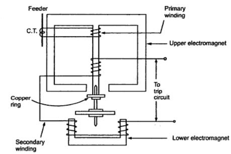
These type of relays are used in the feeder protection and the scheme is called Translay scheme. In this scheme, two such relays are employed at the two ends of feeder as shown in the Fig. 3.

The secondaries of the two relays are connected to each other using pilot wires. The connection is such that the voltages induced in the two secondaries oppose each other. The copper coils are used to compensate the effect of pilot wire capacitance currents and unbalance between two currents transformers.
Under normal operating conditions, the current at the two ends of the feeder is same. The primaries of the two relays carry the same currents inducing the same voltage in the secondaries. As these two voltages are in opposition, no current flows through the two secondaries circuits and no torque is exerted on the discs of both the relays.
When the fault occurs, the currents at the two ends of the feeder are different. Hence unequal voltages are induced in the secondaries. Hence the circulating current flows in the secondary circuit causing torque to be exerted on the disc of each relay. But as the secondaries are in opposition, hence torque in one relay operates so as to close the trip circuit while in other relay the torque just holds the movement in unoperated position. The care is taken that at least one relay operates under the fault condition.
Role of copper ring : Mainly relays may operate because of unbalance in the current transformers. The copper rings are so adjusted that the torque due to current induced in the copper ring due to primary winding of relay is restraining and do not allow the disc to rotate. It is adjusted just to neutralise the effect of unbalance between current transformers. The copper rings also neutralise the effect of pilot capacitive currents. Though the feeder current is same at two ends, the pilot capacitive currents may allow in the pilots. This current leads the secondary voltage by 90o. The copper rings are adjusted such that no torque is exerted on the disc, due to such capacitive pilot currents, by adjusting the angle between the induced current in the disc and secondary current to be 90o.
The advantages of this scheme are,
1. Only two pilot wires are required.
2. The cost is very low.
3. The current transformers with normal design can be employed.
4. The capacitive effects of pilot wire currents do not affect the operation of the relays.
Protection of Transmission lines:
Protection of Lines Based on Unit Principle
The unit protection responds to internal faults only. The use of channel to compare conditions at the terminals of a power line, provides the only selective means of high-speed clearing of end zone faults. In many ways pilot protection is analogous to differential protection of buses , transformers and machines.
The advantages of high speed simultaneous clearing of all terminals are :
- Limits of possibilities of conductor burn down due to overloading and in general minimizes damage to the line.
- Improves transient stability of system by quick disconnection of faulty line.
- Permits high speed reclosing, which is successful, will improve transient stability or minimize outage time or poor voltage conditions on portions of the system load.
Unit type feeder protection includes pilot wire protection and carrier current protection. Merz-price or differential circulating current protection was widely used in U.K and U.S.A. In earlier years d.c. pilot schemes were used. Now they are replaced by A.C. pilot schemes discussed in this section.
1. Pilot Protection Using Circulating Current Differential Relaying
The differential circulating current protection principle can be readily applied to feeder protection. Two CT's are connected in each protected line, one at each end. Under healthy/external fault. conditions the secondary currents are equal and circulate in pilot wires. The relay is connected between equipotential points of pilot wires. For external faults and normal condition the differential current of two I1-I2 CT's is zero and relay does not operate. During internal faults this balance is disturbed and differential current flows through the relay operating coils.
The circuit breakers at two ends separated by a long distance, there is a need to have relaying going at each end associated circuit breaker. In line protection (Fig. 1), relaying point falls in the middle of the line. This means added difficulties.

Fig. 1 Pilot wire protection of line.
To solve this problem the circuit is modified (Fig. 2) by providing two relays. one at each end.

Fig. 2 Use of two relays, one at each end.
Another method (Fig. 3) is by using split pilot principle which uses a three core cable as pilot.

Fig. 3 Pilot wire relaying with split pilot connection using 3-core cable for pilot connections.
Pilot Wire Relaying using voltage balance. In this method the secondary currents are replaced by or converted to an equivalent voltage source of fairly low impedance. The equivalent at two ends are compared as shown in Fig. 4. For health condition., no current flows through the relay coils. During internal fault current circulates through relay coil. Voltage balance system is a basically a differential system.

Fig. 4 Principle of voltage balance
Discriminating factor. Operating current at one terminal or an internal fault to an external fault with same primary current applied from that terminal.

Fig. 5 Discriminating factor
Referring to Fig. 6, consider a current differential scheme.

Fig. 6 Current differential scheme
Let Io be relay operating current, I be the primary current at one end. Keeping primary current I the same, let IOI be the current in relay for internal fault and IOE be current in relay for external fault. Then IO is plotted against fault current. The ratio of IOI and IOE gives discrimination factor. It is observed that beyond a certain value of fault current, the relay loses stability and operates for external faults. (Ref. Fig 30-12 Point of stability)
Transley System. This is based on differential balance voltage principle. It has telephone lines as pilot wires. Advantages of higher currents can be used. Arrangement consist of induction relays at either ends. Schematic diagram is shown in Fig 7.

Fig. 7 Transley system of balance voltage protection
Limitation of Pilot Wire Protection of Line. Pilot protection needs additional expenditure of pilot wires, the pilot wires need supervision to check. Open circuits and short circuits on pilot wires lead to relay failure.
The pilot wires are put at the same time along with power conductors. In cable systems, pilot cables are put in the same trench of power cable.
For short lines of less than 16 km the pilot wires give most economical form of high speed relaying. For line upto 16 km pilot wire protection is popular. It used even for lines upto 50 km. in rare cases. Beyond the length of 16 km. carrier current pilot relaying is more economical and preferable.
Voltages are induced in pilot wires due to the field of power conductors. This voltage should be limited to 5-15 volts.
Overhead pilot wires are exposed to lightening and high voltage surges. They must be protected by means of lightning arresters. Similarly they should not come in contact with power circuit. According to the rules the voltage across pilot is limit to about 200V and current to 200mA.
Pilot Supervision. If pilot circuit opens or shots, relaying system fails. The effect as follows :

To avoid this trouble, automatic supervision is usually applied along with overcurrent fault detectors to prevent wrong tripping.
Summation Circuits
The need to economize in the pilot cores has resulted in the use of current summation devices so that the polyphase line currents may be reproduced as a single-phase quantity. This enables the comparison over the pilot channel to the effected on single phase basis and the pilot cores to be reduced to a minimum of two.
Most summation devices include transformers and can, therefor, be used to reduce the burden imposed by the pilots on the current-transformer by changing the impedance levels. A further advantage is the possibility of isolating the current transformers from the pilots. This enable the current-transformers to be earthed and the pilots to be without earth.
Summation-transformers
The most common device in use is the "Summation-transformer", which is shown in its simplest from in Fig. 8. A common primary-winding is connected to the line current-transformer outputs, each phase energizing a different number of turns, from line to neutral. The arrangement gives an equivalent secondary output for the various types of fault, as shown by the table of Fig. 8 ; these can be easily be derived for any tripping arrangement by construction of the equivalent ampere turn vector diagram. Such devices are not perfect as there are complex fault conditions, such as 2 : 1 : 1 fault-distribution on Y-B-R phase with equal R-Y and Y-B sections, which will give no output. Another example of the limitations of summation transformers is a double earth fault with a resistance earthed neutral. In the ratio of phase fault current to earth fault current is of the right order, it is possible with some double earth-fault, for the output to be zero or very small.

2 comments:
nice for sharing !! but its a totaly copy paste of SUNIL.S.RAO BOOK!!!
I Having 1425 KVA alternator can you give me calculation and testing procedure for same
Post a Comment