Overcurrent IEC characteristics


Types of O/L Relays:-


1) Inverse
definite minimum type relays (IDMT):-
a)
Normal Inverse
i)
3.0 sec relays - i.e. 3.0 sec. at ten times pickup with T.L of 1.0
ii)
1.3 sec relays - i.e. 1.3 sec. at 10 times pickup
b)
Very Inverse relays
c)
Extremely Inverse relays
2) Definite
Time Relays
Instantaneous highest O/L relay
supplementing the above O/C relays. By providing a timer, the required time
delay can be obtained.
The O/L, E/L relays are used for
line protection (for 11KV to 132KV) and for Transformer Protection.
O/C relaying is very well suited to distribution system
protection for the following reasons:-
1.
It is basically simple and inexpensive
2.
Very often the relays do not need to be directional and
hence no PT supply is required.
3.
It is possible to use a set of two O/C relays for
protection against inter-phase faults and a separate O/C relay for ground
faults.
Pick-up Setting
For coordination of the inverse
time O/C relays, the pickup current and time dial setting are to be choosen.
The pickup of the relays must be choosen such that it will operate for all
short circuits in its own line and provide backup for adjoining lines, keeping
in view of maximum full load current.
O/C relay
Pickup setting = I max.load
E/F Relay
Pickup setting = 20% of rated
current.
For the E/F relay, the load
current is not a factor in the selection of pickup settings and is normally set
at 20% of rated current.
Time Settings
The
actual operating time of the O/C & E/F relays can be varied by proper
selection of the ‘Time Dial Setting’ which is selectable from 0.1 to 1.0.
Time
dial settings are to be chosen by having proper coordination and gradation in
the system. Gradations between successive relays are obtained by ‘Selective
time interval’ which is usually set between 0.3 to 0.4 Sec.
The operating time of various
types of IDMT relays are in the sketches. Also can be obtained by the formulae:
-
Normal
inverse : t = 0.14 x TL
(PSM)0.02 - 1
Very
inverse : t = 13.5 x TL
PSM - 1
Extremely
inverse : t = 80 x TL
(PSM)2 - 1
where PSM = Fault
Current/(C.T.Ratio x Plug Setting)
Calculation
example for O/L & E/L relay on line/Transformer:
For remote bus fault, fault current through the protected
element
= 3-Phase : 3000 A (Assume)
SLG : 2500 A (Assume)
O/L
relay:
Adopted C.T.Ratio on protection line = 600/1 A (Assume)
Pickup Setting for O/L relay = 1 A (Plug Setting)
PSM for O/L relay = 3000
---------- = 5
(600/1 x 1)
Actual time of operation for O/L & E/L relays is
generally set to grade with the down side system.
Assume time setting required = 0.4 Sec.
0.14
Actual Time of Operation (ATO) : 0.4 =
------- x TL (For Normal Inverse)
(5)0.02-1
0.4 x 0.0327
T.L = ------------- = 0.093
0.14
Set Time Dial (TL) for O/L relay =
0.1
Actual Time of Operation (ATO) for O/L relay 0.14
(With T.L:0.1) T
= ---------- x 0.1 = 0.42 Sec.
(5)0.02-1
E/L relay:-
Pickup setting for E/L relay = 0.2 A
2500
PSM for E/L relay = ------------
= 20.8
600/1 x 0.2
If PSM exceed 20, set PSM = 20
Actual Time of Operation (ATO)
0.14
for E/L relay =
0.4 =
---------- x T.L
(20)0.02-1
T.L =
0.4 x 0.0617
--------------
= 0.176
0.14
Set T.L = 0.2
Actual Time of Operation for E/L relay with T.L = 0.2
0.14
T = ------------
x 0.2 = 0.45 Sec.
(20)0.02-1
Selective time interval:
The time interval between two
successive breakers to provide the required selectivity is termed as selective
time interval.
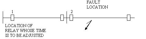
The operating time of the relay
at 1
i.e., t1 = t2 + b2 + 01 + f
where t2 = operating time of
relay at 2
b2 = breaker operating time at 2
f
= factor of safety time
01 = overtravel time of relay at 1
The selective time interval S = b2+01+f = 0.3 to 0.4 Sec.


3 comments:
Your blog shared the information about Types of Over Current Relays. It's very usefull information but you have to some thing else about this.In power system networks, protection has to be designed such that protective relays isolate the faulted portion of the network, to prevent equipment damage, injury to operators and to ensure minimum system disruption enabling continuity of service to healthy portion of the network. If you have to know more, Please visit Relay Coordination
Great Blog,Thanks for sharing such beautiful information with us. I hope to will share some more information about arc flash protection. Please visit our website arc flash protection
Thanks for sharing this informative post with us. I would like to share that Paraflex is leading cable & wire manufacturers in India.
Post a Comment